

Article Abstract
Rogers PCB materials are widely used in high-frequency and high-speed electronic applications where standard FR4 boards fail to maintain signal integrity. This article explores how Rogers PCB technology works, why it is preferred in RF and microwave circuits, and how engineers can solve common design challenges such as signal loss, dielectric instability, and thermal management. It also provides practical comparisons, design insights, and application guidance to help engineers and buyers make informed decisions.
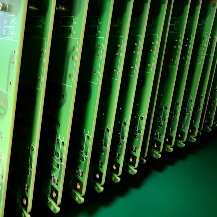
A Rogers PCB is a high-performance printed circuit board built using specialized laminates developed by Rogers Corporation. Unlike traditional FR4 materials, Rogers laminates are engineered for stable dielectric constant (Dk), low signal loss, and excellent thermal reliability. These properties make them ideal for high-frequency applications where signal integrity is critical.
Common Rogers materials include RO4350B, RO4003C, and RT/duroid series, each optimized for different RF and microwave design requirements.
In modern communication systems, even minor signal distortion can lead to major performance issues. Rogers PCBs address this problem through controlled dielectric behavior and low loss tangent values.
These advantages make Rogers materials essential in RF engineering, where precision and reliability are non-negotiable.
| Feature | Rogers PCB | FR4 PCB |
|---|---|---|
| Dielectric Constant Stability | Very High | Moderate |
| Signal Loss | Very Low | Higher |
| Frequency Range | Microwave / RF (GHz) | Low to Mid Frequency |
| Thermal Performance | Excellent | Standard |
| Cost | Higher | Lower |
While FR4 is suitable for general electronics, Rogers PCB is specifically engineered for performance-critical environments.
Rogers PCB materials are widely used in industries requiring high-frequency precision:
These applications demand stable signal transmission with minimal distortion, making Rogers materials the preferred choice.
Designing with Rogers PCB requires careful attention to electrical and mechanical parameters. Below are essential best practices:
Improper design can lead to signal reflection, insertion loss, and reduced system efficiency.
Despite its advantages, Rogers PCB design presents several challenges:
Engineers often adopt hybrid designs to balance performance and cost efficiency without compromising signal integrity.
Selecting the correct Rogers laminate depends on application requirements:
Key selection factors include frequency range, dielectric constant, thermal conditions, and budget constraints.
Q1: What makes Rogers PCB better than FR4?
A: Rogers PCB offers lower signal loss, better dielectric stability, and superior performance at high frequencies compared to FR4.
Q2: Is Rogers PCB only used in aerospace?
A: No. It is widely used in telecommunications, automotive radar, and commercial RF systems as well.
Q3: Why is Rogers PCB more expensive?
A: The cost comes from advanced material composition and specialized manufacturing requirements.
Q4: Can Rogers PCB be mixed with FR4?
A: Yes, hybrid stack-ups are commonly used to optimize cost and performance.
Q5: What frequency range can Rogers PCB support?
A: Depending on the material, it can support from several GHz up to microwave frequency bands.
Rogers PCB technology plays a critical role in modern high-frequency electronics, enabling stable and efficient signal transmission in demanding environments. From 5G networks to aerospace systems, its advantages in dielectric stability and low loss performance make it a cornerstone of advanced circuit design.
For engineers and procurement teams seeking reliable high-frequency PCB solutions, working with experienced manufacturers ensures optimal performance and manufacturability. Hayner PCB provides customized Rogers PCB fabrication solutions tailored to complex RF and microwave applications. If you are planning your next high-performance project, Hayner contact us to discuss your requirements and receive expert engineering support.


 devices?")


